The objective of this tutorial is to demonstrate the main concepts and techniques of using AdvaNum Milling CAM and AdvaNum NC Verification 4.0. In the course of this tutorial we will create a sample workpiece drawing that will be converted into CNC program. The CNC program then will be simulated and verified using AdvaNum NC Verification product.
This tutorial assumes that you are familiar with using Microsoft® Windows™ operating system. For more in-depth information about using AdvaNum Milling CAM and AdvaNum NC Verification please refer to respective User's Guide manual.
In the section we will create a new workpiece drawing that will be translated into a part program. Please follow the steps below:
1.1. Start AdvaNum Milling CAM 4.0.
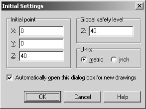
1.2. In the AdvaNum Milling CAM window choose File | New Drawing menu command. This will open an empty drawing window and pop up Initial Settings dialog box. Initial point is used to transfer the tool between tasks (contours, pockets, procedures and CodeBlocks). Global safety level is a level above workpiece surface at which tool can be moved without colliding with the workpiece. Set Initial point to (0, 0, 40) and Global safety level value to 40. Click OK button.
1.3. Add Entity dialog box will automatically appear allowing us to insert new lines, arcs and circles into the new drawing we are creating. Make sure a Pin button in the left lower corner of the dialog box is depressed, which will allow specifying more than one entity at the same time. To add first line, set Entity type to Line, Definition type to X, Y of End and specify X = 0; Y = 100 as end point of the line. Click Add button to insert the line to the drawing. In the same way add three more lines, with the end points at (150, 100), (150, 0) and (0, 0).
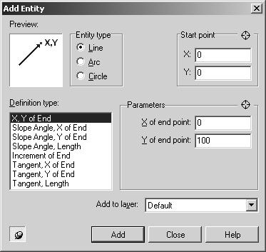
1.4. Now let us add a circle to the drawing. Set Entity type to Circle and Definition type to Center, Radius. Use the following values for the parameters: Radius = 20; X of Center = 75; Y of Center = 50. Click Add button and then Close button to close Add Entity dialog box.
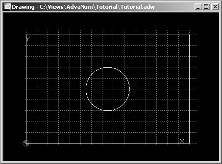
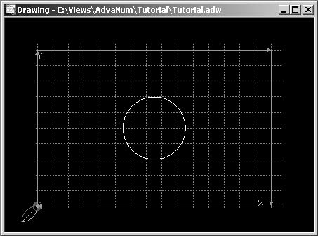
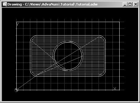
1.5. After we have added the four lines and the circle, our workpiece drawing should look like that.
1.6. By now we have finished creation of a basic workpiece drawing that we will use to generate a part program.
Contour defines movements of tool along a continuous path at specified level by Z-axis.
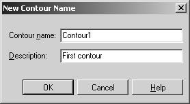
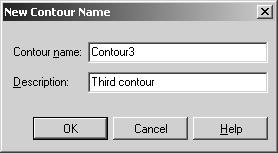
2.1. To create a contour, choose Task | Create New Task | Create New Contour. In the New Contour Name dialog box, enter the contour name (Contour1) and an arbitrary description. Click OK button to close this dialog box.
2.2. Now click the left mouse button over the left vertical line in the drawing. It will change it color indicating that it has been added to the contour. Next, click left mouse button over the top horizontal line to add it to the contour as well. Finally choose Select | Select Automatically menu items to add the remaining two lines to the contour. Automatic selection can be performed when there are two or more selected entities and hence contour direction is determined. Finish contour creation by using Select | Finish Contour Selection menu command. After this command is selected, the Contour Properties dialog box will appear allowing us to specify detailed information about the contour.
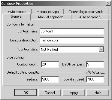
2.3. On General page, we need to change information about Side cutting. Setting Contour depth to 20 and Depth per path to 5 will generate 4 passes of tool around the contour at different levels by Z-axis. You can also set Feedrate and Spindle speed to desirable values or use Cutting Wizard to find out recommended values for you machine, workpiece and tool combination.
2.4. Now let us switch to Manual approach page where we can manually specify the set of points a tool will pass through before approaching the contour. We will specify only one such point. Click a green Plus button and specify the following values: X = -10, Y = -10, Z = 40.
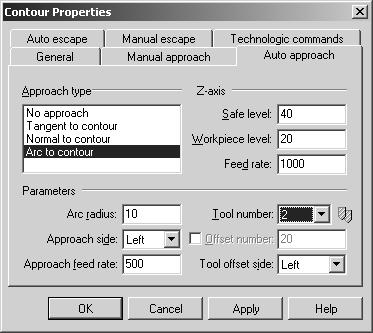
2.5. Now we need to switch to Auto approach page to specify a smooth automatically generated trajectory by which the tool will approach beginning of the contour from the last point of manual approach. Set Approach type to be Arc to contour and specify parameters as shown on the picture. Safe level is the level defined by Z-axis at which it is safe to approach the workpiece. Workpiece level defines the Z-axis level of the contour.
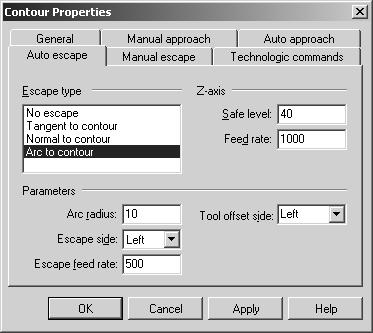
2.6. In a similar way, we specify parameters for automatically generated escape trajectory from the contour on Auto escape page. Please specify parameters for auto escape as shown on the next picture.
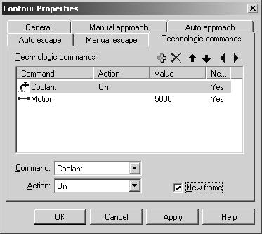
2.7. And finally we can specify optional technological commands and condition for each element of the contour on Technologic commands page.
2.8. Press OK button to finish specifying the contour parameters. After that, the contour name will appear in the Task List.
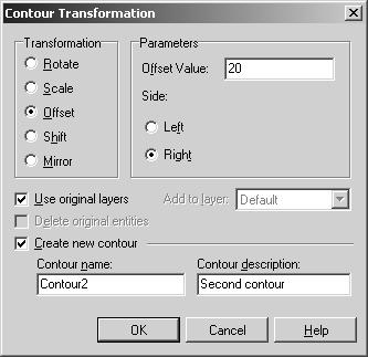
2.9. Now we will define second contour as the result of transformation of the first contour. Select Contour1 in the Task List and use Edit | Transformation menu command. In the Contour Transformation dialog box, select Offset transformation method, set Offset value to 20 and Offset side to Right. Also specify name and description for the new contour that will be created. Click OK button to perform actual transformation. The new contour will be created and added to the drawing.
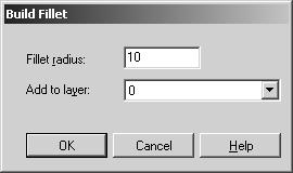
2.10. After that we want to add fillets to the newly created contour. While Contour2 is selected in the Task List, choose Edit | Build Fillet menu command. This will open Build Fillet dialog box. Set Fillet radius to 10 and click OK. Repeat this procedure three more time to build the fillets between all contour's lines.
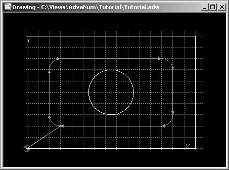
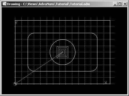
2.11. After that the drawing will look as shown on the picture.
2.12. And finally we need to create third contour consisting only of one circle we have defined. Select Task | Create New Task | Create New Contour menu command. Specify third contour name and description.
2.13. Now click left mouse button over the circle in the drawing window to add it to the contour and use Select | Finish Contour Selection menu command. Click OK button in the Contour Propertied dialog box that will come up without specifying any additional parameters. Now we have three contours defined.
Pocket defines movements of tool within specified boundaries by X, Y and Z-axes.
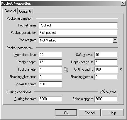
3.1. Let us create a pocket with Contour2 as a boundary and Contour3 as its island. To create this pocket use Task | Create New Task | Create New Pocket menu command. On General page specify parameters values as shown on the picture.
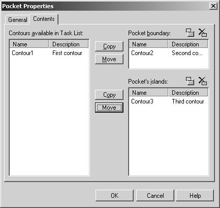
3.2. To specify the pocket's boundary contour and island switch to Contents page. Use appropriate Move buttons to choose Contour2 as the pocket's boundary contour and Contour3 as the pocket's island.
3.3. After you click OK button you will see the tool movements for the pocket in the drawing. Please notice that these movements are only displayed when pocket is selected in the Task List.
Procedure defines movement of tool using a predefined pattern.
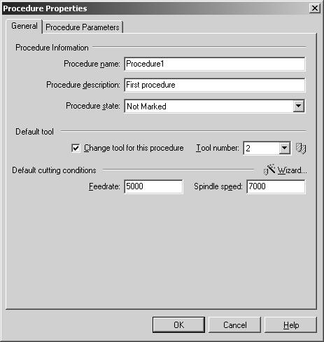
4.1. We will use a procedure to mill a square shaped opening inside the circle. To create a new procedure, use Task | Create New Task | Create New Procedure menu command. On General page we specify such parameters as a tool number to be used and default federate and spindle speed.
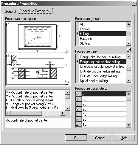
4.2. To select the procedure type and specify its actual parameters, switch to the Procedure Parameters page. In Procedure group select Milling, and choose Rough Square Pocket Milling in the Procedure type list box. Then specify the following parameters for the procedure:
| Param | Value |
|---|---|
| X | 75 |
| Y | 50 |
| U | 20 |
| V | 20 |
| I | 40 |
| R | 20 |
| Z | 10 |
| W | 3 |
| D | 2 |
| K | 100 |
| C | 0 |
| F | 3000 |
| E | 3000 |
| J | 1000 |
4.3. To select the procedure type and specify its actual parameters, switch to the Procedure Parameters page. In Procedure group select Milling, and choose Rough Square Pocket Milling in the Procedure type list box. Then specify the following parameters for the procedure:
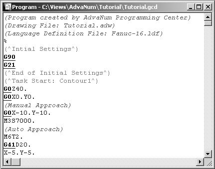
5.1. Now when we have defined all tasks we can translate them into a part program. First save your drawing by choosing File | Save menu command. Then use Task | Translate All Tasks menu command to generate the part program from the tasks we have defined. After translation is performed, all translated tasks will be marked as Translated in the Task List. The tasks will be translated in the order they are arranged in the Task List. You can change task order using Task | Move Task Up and Task | Move Task Down commands. Using this command will also move task translation in the program. Now save you program using File | Save menu command again.
Using AdvaNum NC Verification program simulation features you inspect the tool path and model of the workpiece that will result from actual execution of the program on a machine tool.
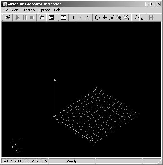
6.1. To perform program simulation, choose Program | Simulate Program menu command. This will open AdvaNum Graphical Indication window where the simulation results will be displayed.
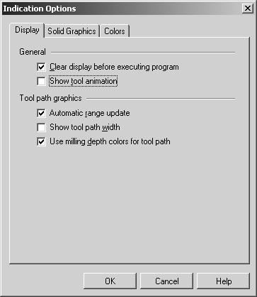
6.2. To specify simulation parameters choose Option | Indication Options menu command. That will display Indication Options dialog box. On the Display page of this dialog box, make sure only Clear display before executing program. Automatic range update and Use milling depth colors for tool path boxes are checked and then click OK button.
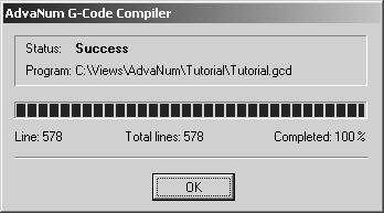
6.3. Choose Program | Simulate menu command to actually start the program simulation. This will activate AdvaNum G-code Compiler, which converts the program text into binary format that can be executed by AdvaNum CNC Processor. Click OK button to close the compiler window.
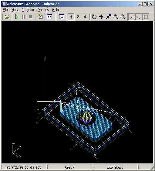
6.4. Shortly after that, AdvaNum Graphical Indication will start receiving the simulation data. After program simulation is over you will see the resulted tool path displayed in AdvaNum Graphical Indication window.
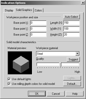
6.5. Now we want to display a model of the workpiece that will be created as result of program execution. To specify parameters of the workpiece model choose Option | Indication Options menu command. That will display Indication Options dialog box. Switch to the Solid Graphics page of this dialog box. Specify the following values: Base point = (0, 0, 0); Length = 150, Width = 100; Height = 20. Then click Suggest button next to Quality label to determine an optimal quality level of the solid model for your machine. Click OK button to close the dialog box.
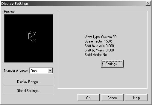
6.6. To display solid model, choose View | Display Settings. The Display Settings dialog box will be displayed.
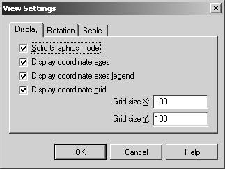
6.7. Click Settings button to display View Settings dialog box. In this dialog box, check Solid Graphics Model check box. Click OK buttons in both dialog boxes.
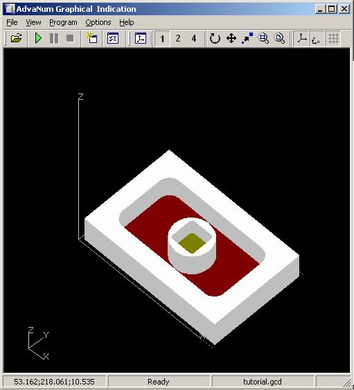
6.8. The solid model of workpiece will be built and displayed in AdvaNum Graphical Indication window.
Now we have followed all basic steps from creating a new drawing to translating it into NC program and simulating the created program. You can also use AdvaNum NC Verification G-code debugging features to inspect the logic of the NC program, however this topic is not covered in this tutorial. For more information please refer to AdvaNum NC Verification User's Guide manual.